

Sample TMD: Tuned Mass Damper (TMD) Response Control Building
Basic Information | Commentary
Basic Information
Building Overview
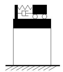
Tuned Mass Damper (TMD) is a system that reduces resonant vibration during earthquakes by installing a weight at the top of the building and setting its sway period to a value close to the natural period of the building.
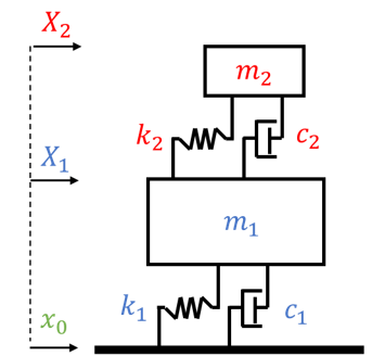
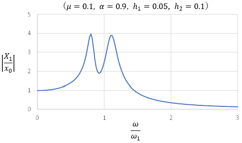
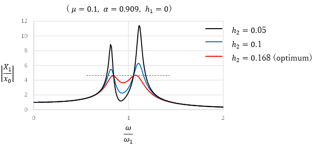
Let the building be the main vibration system (mass m1, natural circular frequency ω1, damping constant h1) and the TMD be the secondary vibration system (mass m2, natural circular frequency ω2, damping constant h2). The following resonance curve is obtained by determining the ratio (absolute response factor) of the response X1 of the main vibration system to the harmonic ground motion of ground motion amplitude x0. From this, the response factor of the main vibration system has a resonance curve with a valley near the frequency ratio of 1, and two peaks are formed on both sides of the valley. Here, the mass ratio μ = m2/m1 = 0.1, the frequency ratio α = ω2/ω1 = 0.9, the damping constant of the main vibration system h1 = 0.05, and that of the secondary vibration system h2 = 0.1.
When the damping constant of the main vibration system h1 = 0, resonance curves with varying damping constants of the TMD always pass through the same two points. This point is called the fixed point, and the method of determining the optimal TMD frequency ratio and damping constant using the fixed point is called the fixed point theorem.
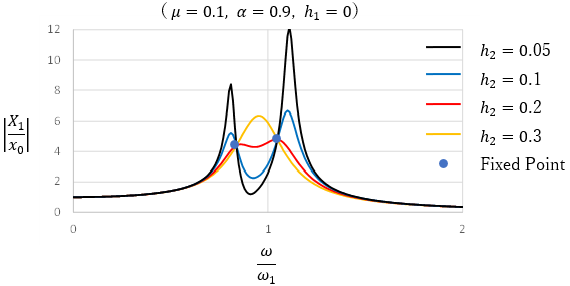
In the fixed-point theorem, the optimum value is defined as the frequency ratio at which the two maxima of the resonance curve are the same. Furthermore, the damping constant at which the fixed point becomes the maximum value is determined as the optimum value. This is the optimum tuned resonance curve that reduces the response field ratio the most.
From the fixed-point theorem, the optimal frequency ratio is
![]()
The optimum damping constant is
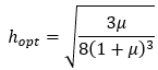
The derivation of the equation is summarized in “Basic Theory of TMD”.
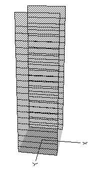
The following is an example of a TMD in a 20-story high-rise building. The building and the TMD (21st layer) are modeled as an elastic-shear lumped mass model. The elastic springs and damping (dashpot elements) of each layer are considered as separate elements, and each lumped mass model is placed in parallel. Please refer to the building information for model parameters.
Database
Building information includes the source information of creating input data of STERA_3D.
| Building Information (*.pdf) | Input file (*.stera) | STERA_3D version | Author | Date | |
|---|---|---|---|---|---|
| 1 | B01_TMD_20F | B01_TMD_20F | 11.5 | Taiki Saito | 2024.7.21 |
Go to top of page
Commentary
Go to top of page